Concrete batching plant cement silo can be set near the plant alone or can be located on the upper part of the concrete batching plant.
The cement warehouse of concrete batching plant can be divided into two types: bagged cement warehouse and bulk cement warehouse. The warehouse of bulk cement is usually a silo storage cylinder called cement silo.
After 3 days of reviewing the information about cement silos in concrete mixing plant, I believe I have a more comprehensive understanding of it. I will give you a detailed introduction.
Here are the details of the research.
Composition of concrete batching plant cement silo
1.1 Unloading room
1.2 Silo
Storage capacity of cement silos
2.1 Cement storage period
2.2 Cement silo storage capacity
Determination of the volume and geometry of cement silos
3.1 The layout of the silo
3.2 Silo volume
1. Composition of concrete batching plant cement silo

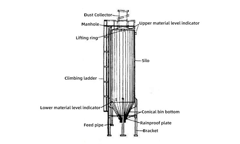
Concrete batching plant cement silo mainly includes two parts: unloading room and silo.
1.1 Unloading room
The unloading room includes unloading shed, unloading pit, and control room, which mainly completes the unloading process of bulk cement and conveys cement to the silo roof. According to the feeding method of bulk cement, the unloading process can be divided into two categories: train unloading and car unloading, which are equipped with different types of unloading rooms.
1.2 Silo
Silo includes silo roof room, silo body, and silo bottom supply room. After the bulk cement is discharged and transported to the silo roof room, it is stored in the silo cylinder according to varieties and specifications respectively. When being used, the cement is transported to the designated place or directly supplied to the transportation machinery by the feeding and conveying equipment in the bottom feeding room.
1.2.1 The silo roof room
It is located at the top of the silo, in which the cement feeding equipment and dust collector are mainly set up.
The following issues are mainly considered in the process design of the silo roof room.
(1) Determine the type of cement feeding equipment.
(2) Determine the dust collector system.
(3) Open the inlet hole and observation hole in the roof of the silo. The inlet hole is designed to be 700×700mm and the observation hole is designed to be Φ200mm.
(4) In addition to the local insulation of dust collector in cold areas, the silo roof is generally not equipped with heating.
(5) Double-row silo can use the heart silo part to open the installation hole.
1.2.2 Broken arch device
Due to the effect of friction, adhesion, and bonding between the cement particles or between the particles and the wall, the cement often forms an arch at the mouth of the bucket. In the design of a silo, it is necessary to consider the measures to prevent arching and the device to break the arch once it is formed.
General measures to prevent arching: take measures in the hopper type to prevent arching; add external force to prevent arching.
The common method to break the arch in a cement silo is inflatable blowing or inflatable fluidization.
2. Storage capacity of cement silos
2.1 Cement storage period
According to P. Barnes [1], the storage period of cement in concrete batching plant is shown in Table 2-1.
| Shipping Method | Railroad | Waterway | Highway | Highway |
| Speed | / | / | >50km | <50km |
| Storage period | 20-30 | 10-20 | 7-10 | 5-7 |
2.2 Cement silo storage capacity
2.2.1 Cement storage capacity calculation formula
Q=qnG/(1-η)
In the formula
Q – cement storage capacity (t)
q – cement amount in the average mix ratio when the most unfavorable combination of product varieties occurs in production (t/m³)
n – storage period
G – daily production of concrete (m³/d)
η – cement loss rate, for bulk cement, is 0.5-1%.
2.2.2 Maximum cement storage capacity calculation formula
Qm=nγVe
Qm – maximum cement storage capacity
n – number of cement silos
γ – cement volumetric weight (Table 2-2)
Ve – effective volume of cement [3.2.2]
| Cement varieties | Volumetric weightγ(t/m³) | Specific gravity | Often taken volumetric weightγ(t/m³) |
| Ordinary cement | 1.2-1.4 | 3.0-3.2 | 1.3 |
| Slag cement | 1.1-1.3 | 2.8-3.0 | 1.25 |
Determination of the volume and geometry of cement silos
3.1 The layout of the silo
Follow the principle that the conveying equipment used is the least.
It is generally required to
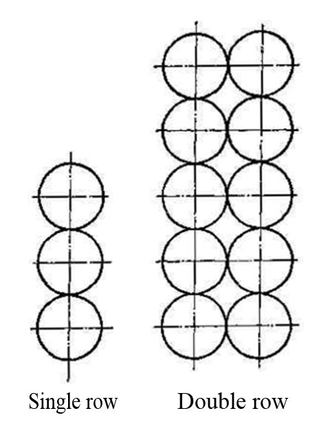
1. According to the number of silos, the silo will be arranged as a single or double row layout.
2. The silo is as near as possible to the unloading room, and the axis of single and double row type should be arranged perpendicularly with the railroad line as far as possible.
3. The total length of the silo along the axis should not exceed 50 meters in general. If more than 50 meters, structural expansion joints should be set.

3.2 Silo volume
| Silo inner diameterD(m) | Silo heighth(m) | VolumeV(m³) | Effective volume(m³) | Storage capacity(t) | Storage capacity(t) |
| Ordinary cement | Slag cement | ||||
| 5 | 13 | 260 | 230 | 300 | 290 |
| 6 | 15 | 430 | 380 | 500 | 475 |
| 7 | 18 | 700 | 600 | 780 | 750 |
| 8 | 20 | 1000 | 850 | 1100 | 1060 |
| 10 | 24 | 1900 | 1700 | 2200 | 2120 |
3.2.1 Silo volume(V) calculation formula
V=(πD^2)(h+D*tanα/6+D*tanψr/6)/4
V – silo volume (m³ )
D – silo inner diameter (m)
ψr – angle of repose, for cement, is 30°
α – inclination angle
3.2.2 Effective volume calculation formula of cement silo
Ve=V*φ
Ve – effective volume of cement
V – volume of silo
φ – filling rate of silo
After reading this article, I believe you have a certain understanding of the composition, storage capacity and volume of cement silos. If you are not sure about cement silos or the calculation of storage volume and capacity, leave a comment and tell me, I will consider writing an article with specific examples.
[1] P.Barnes. Structure and Performance of Cements.


When some one searches for his required thing, so he/she wants to be available that in detail, thus that thing
is maintained over here.